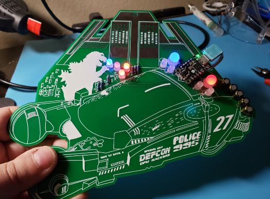
Godzilla vs. Blade Runner Badge Assembly
HOME - DETAILS - PARTS - ASSEMBLY - CODE - I WANT ONE!
This is where you will find detailed step by step instructions on how to assemble the badge.
Assembly steps
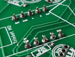
- Solder the Trinket M0 header pins
- The Trinket comes with a single breakable 1x16pin header strip. Break off two 5 pin sections to use.
-
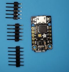
- Save the left over 6 pin male header to use later
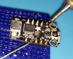
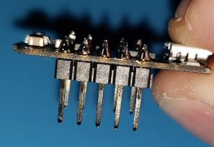
- Place the two five pin header strips into the Trinket PCB inserting the short end into the through holes.
- Solder these header pins on the top of the Trinket PCB
-
-
- Solder the resistors to the Badge
- Place the eight resistors into the badge PCB through holes with the components on the front of the PCB.
-
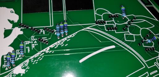
- Bending the resistor legs slightly will hold them in place.
- The direction the resistor is placed does not matter.
-
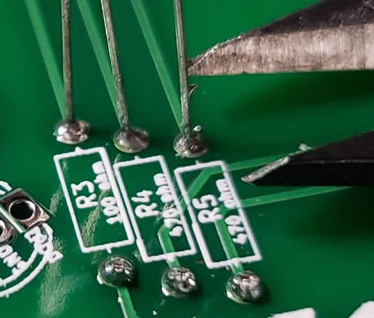
- Be sure that the 100ohm resistor is in the R3 position mark on the back of the PCB.
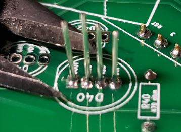
- Solder the resistors on the back of the PCB.
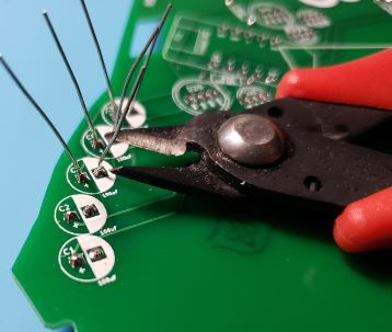
- Cut off the resistor pins close to the back of the PCB (not too close or it will damage your solder joints)
-
- Solder the capacitors to the Badge
- Place the five capacitors into the badge PCB through holes with the components on the front of the PCB.
-
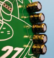
- Bending the capacitor legs slightly will hold them in place.
- The direction the capacitors are placed is IMPORTANT.
- The long leg is positive and the short leg where the 0 is printed on the cap is negative.
- The long positive legs should be nearer to the outside edge of the PCB.
-
- Solder the capacitors on the back of the PCB.
- Cut off the capacitor pins close to the back of the PCB (not too close or it will damage your solder joints)
-
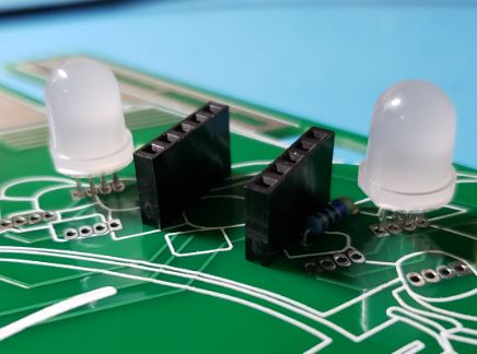
- Solder the female headers to the Badge
- Place the two 5 pin header strips male pins into the badge PCB through holes with the female headers on the front of the PCB.
- Use the left over 6 pin male header from the Trinket to keep these headers at 90 degrees from the PCB.
- The 6 pin male header is the perfect size to represent the trinket for spacing, just plug into the middle of each female header
-
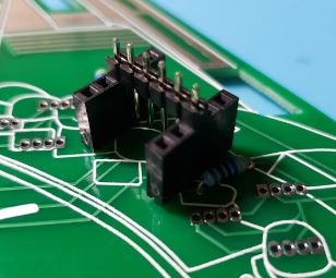
- Place the board down on the headers or use a bit of tape on the front to hold them in place.
-
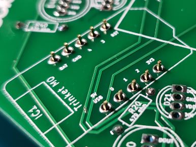
- Solder the headers on the back of the PCB.
-
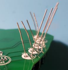
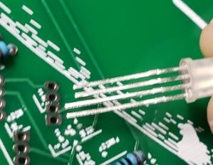
- Solder the NeoPixel LEDs to the Badge
- Place the ten NeoPixel LEDs into the badge PCB through holes with the components on the front of the PCB.
-
- With four legs they should stay in place by friction alone. However, you can bend the LED legs slightly if needed.
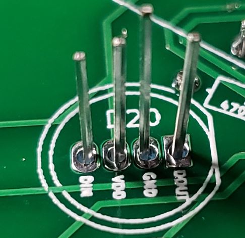
- The direction the NeoPixel LEDs are placed is IMPORTANT.
- On the 5mm LEDs the long leg should go in the through hole that is a rectangle instead of an oval.
- The long leg is on the side of the LED that has a flat notch. The back of the PCB shows where this notch should be aligned.
-
- On the 8mm LEDs the long leg should go in through hole that is the oval pad next to the rectangle one.
- On these bigger LEDs the long leg is pin 2 not pin 1 like the smaller LEDs
- The long leg is on the side of the LED that has a flat notch. The back of the PCB shows where this notch should be aligned.
-
- I would suggest placing and then soldering only a few LEDs at a time because they are very close together.
- Solder the NeoPixel LEDs on the back of the PCB.
- Cut off the LED pins close to the back of the PCB (not too close or it will damage your solder joints)
-
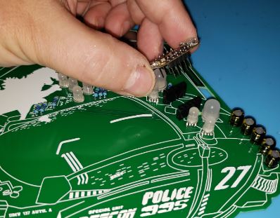
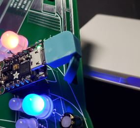
- Insert the Trinket m0 onto the badge
- Place the Trinket m0 male pins into the female headers on the front of the board
- Be sure to align the Trinket with its USB connector towards the edge of the PCB
- Each Trinket has been preloaded with the code to control the badge. See the code link above for details.
-
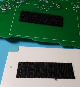
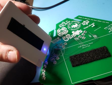
- Attach the Battery to the badge
- Apply the Velcro strip to the badge PCB (Use the soft Velcro here in case you wear the badge without the battery)
- Apply the Velcro strip to the Battery
-
- Feed the Battery cable through the rectangle hole in the PCB
-
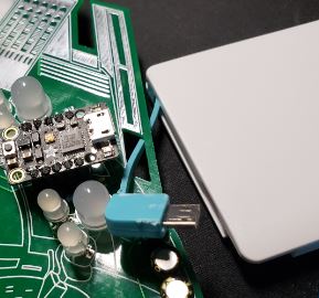
- Connect the Battery cable to the Trinket
- Do this before you attach the Battery to the badge to avoid having to make readjustments
-
- Attach the Battery to the back of the badge by sticking the Velcro strips together
-
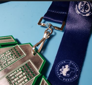
- Attach the Lanyard to the badge
- The Lanyard J Clip should clip into the hole at the top center of the badge PCB
-
- Rock the badge at the CON!
- Touching the Tyrel building will change LED modes.
- One of the LED modes is all off in case you need to quickly turn off without removing the battery.
-